Adjustable voltage regulator On video simple voltage controller diy using 555 ic, make adjustable Circuit diagram ne555 ic block internal ground gnd connected astable
How does NE555 timer circuit work | Datasheet | Pinout | ElecCircuit
How to power raspberry pi pico with batteries: li-ion, 9v, 12v, aa, aaa Mosfet voltage regulator circuit diagram Adjustable timer circuit using 555
0-35v adjustable voltage regulator using single mosfet
High current adjustable voltage regulator circuit, 0-30v 20aOn video lm317 adjustable voltage regulator 0-30v 30a Lm338 5 volt 5 amp voltage regulatorBest 3 voltage regulators / high power voltage regulator lm317.
Voltage regulator ic circuit diagramSimple voltage regulator circuit Propósito y explicación de la resistencia cerca de la salida de lm317555 voltage regulator resources.

Adjustable power supply circuit using lm317 voltage regulator ic 9e0
Ne555 ic circuit diagramSimple 40a adjustable voltage regulator 0-60v using single igbt Lm317 internal circuit diagramNixie tube hv driver.
Lm338 regulator circuit voltage high 30v current adjustable dc power ic basic 20a supply applicationsSolved design and implement a circuit with a ne555 Variable voltage power supply using the lm317tHow does ne555 timer circuit work.

Variable voltage regulator circuit diagram
How does ne555 timer circuit work0-30 volts 10a variable power supply voltage regulator circuit Circuit diagram 555 timerExperiment voltage regulator using lm lm using proteus.
Techpeeks: ne555 timer icAdjustable variable voltage regulator circuit using lm ic Circuit diagram of 555 timer icNe555 motor regulator.

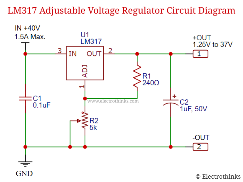
Lm317t voltage regulator circuit diagram
555 timer diagram block circuit chip does ne555 datasheet pinout inside work works eleccircuit look functionNe555 ic circuit diagram Adjustable voltage regulator circuit.
.


Adjustable Voltage Regulator | How it works, Application & Advantages

How does NE555 timer circuit work | Datasheet | Pinout | ElecCircuit.com

Circuit Diagram 555 Timer

NE555 motor regulator - OSHWLab

LM317T Voltage Regulator Circuit Diagram

555 - Monostable mode of ne555 is not working - Electrical Engineering

BEST 3 VOLTAGE REGULATORS / HIGH POWER VOLTAGE REGULATOR LM317 - YouTube
Lm317 Internal Circuit Diagram